Process Control/Redundant Supported products

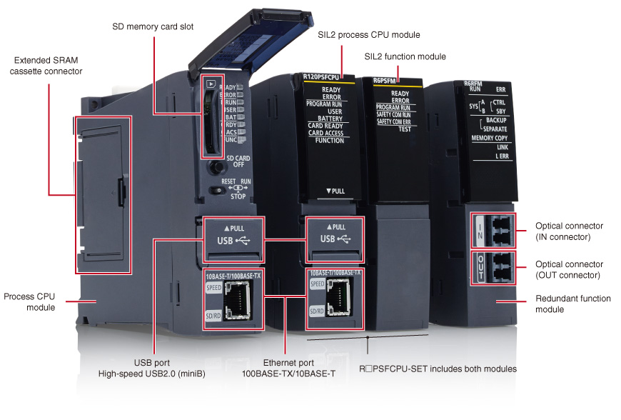
Process CPU module, SIL2 process CPU module, Redundant function module (MELSEC iQ-R Series)
Flexible process control in a cost-efficient automation control solution
The MELSEC process control system consists of specialized controllers specifically designed for use in process automation. The CPUs are highly flexible utilizing standard automation control system features rather than DCS solutions that can be costly to replace and maintain.
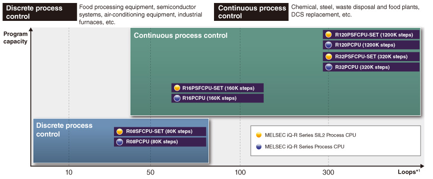
- *1.The maximum amount of usable loops may change depending on the actual program size used. Please refer to the relevant manuals for further details.
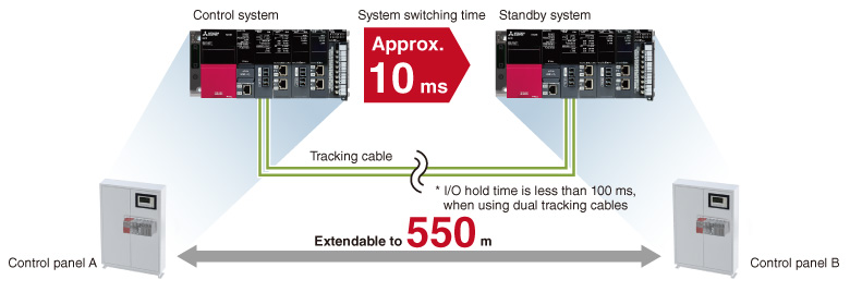
Redundant system remote location and high-speed switching
Optical-fiber tracking cables enable the standby system to be installed in a remote location up to 550 m from the control (primary) system. The tracking cables are immune to noise interference and support fast data transfer rates.
System switching speed from the control system to the standby system has also been improved to speeds of approximately 10 ms, further improving system reliability.
Distributed system deployment with CC-Link IE Controller/Field Networks
By using a media converter, the station-to-station distance on the CC-Link IE Controller Network can be extended up to 15 km and the station-to-station distance on the CC-Link IE Field Network can be extended up to 10 km, allowing distributed configuration of systems.
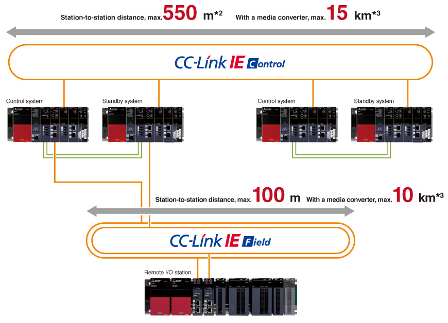
- *2.Because the distance between the redundant systems is limited to 550 m, the station-to-station distance is also limited to 550 m.
- *3.Compatible with industrial media converters manufactured by Mitsubishi Electric System & Service Co., Ltd.
For CC-Link IE Controller Network, please refer to DMC-1000SL-DC. For CC-Link IE Field Network, please refer to DMC-1000SL-DC or DMC-1000TS-DC.
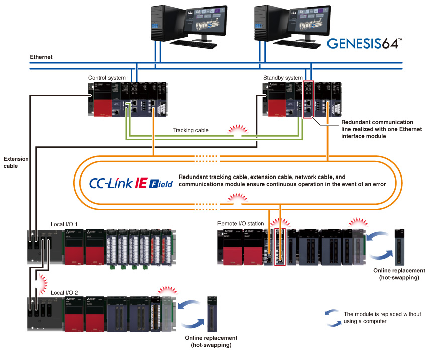
Improve reliability with reduced single-point failure
A multi-level redundant system can be realized by installing dual control systems consisting of the control (primary) and standby CPUs. Combined with a dual extension cable topology for both the redundant extension base units and network cabling of the CC-Link IE Field Networks together with dual remote stations, the risk of singe-point failure can be minimized. Online replacement of cables and modules (hot-swapping) is possible while continuously operating the system when an error occurs, enabling prompt troubleshooting.
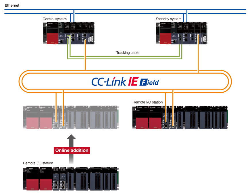
Online addition of a remote I/O station while the system is running
Utilizing dedicated instructions to set parameters of the CC-Link IE Field Network master/local module, remote I/O stations can be added online while the system is running, improving the system availability.
Mixed configuration of SIL 2-supporting and non-supporting modules
The MELSEC iQ-R Series SIL2 redundant system meets global needs by complying with SIL 2*4, which is required in the field of public infrastructure where high reliability is required.
- *4.Since December 2022, SIL 2 compliance has been switched from compliance certification by TÜV Rheinland to self-declaration by our company.
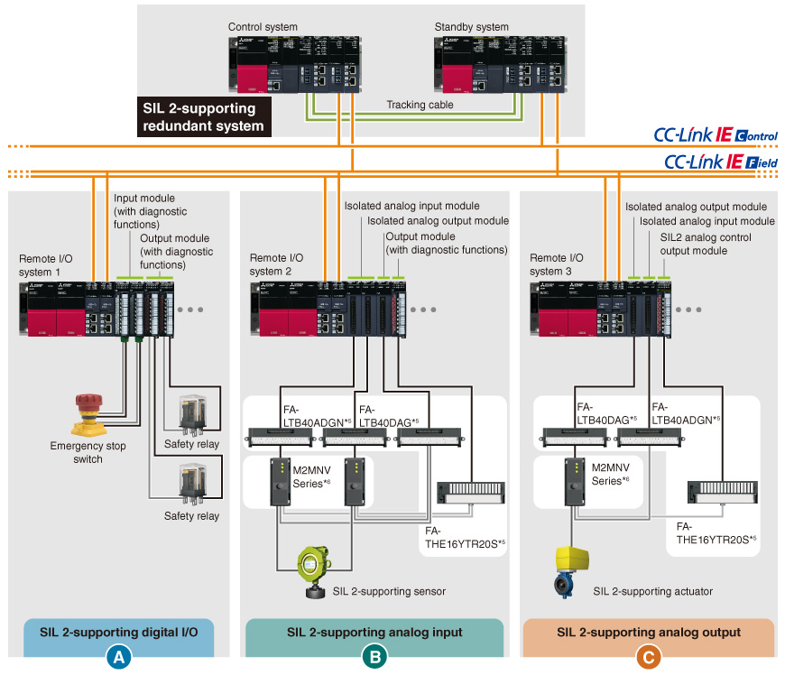
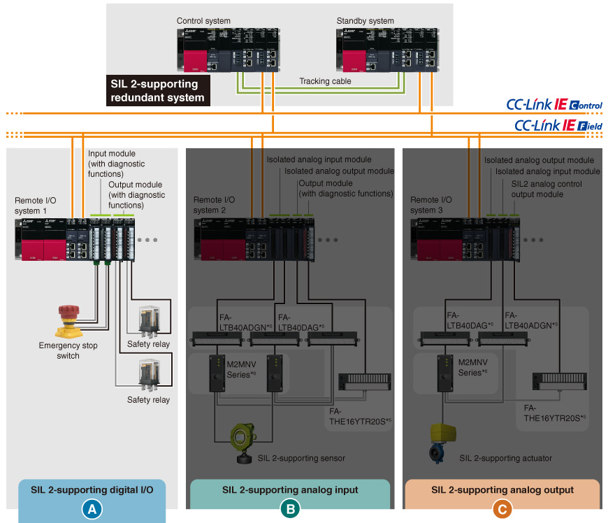
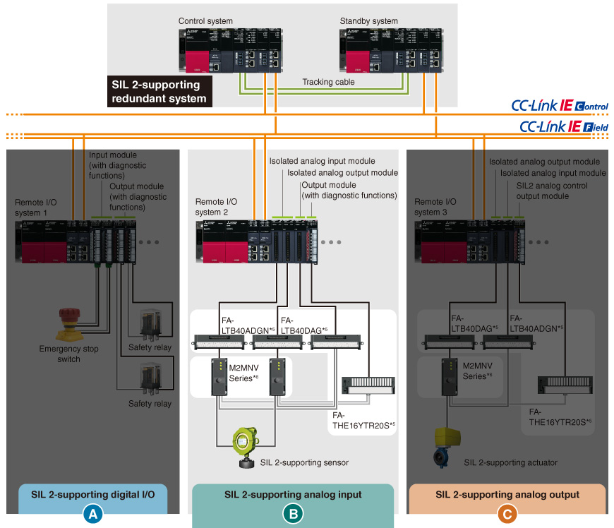
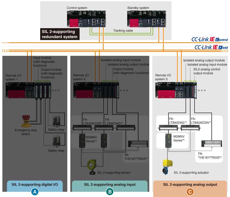


Click on A, B, or C.
SIL 2-supporting safety inputs and outputs are configured by having a set of two input modules (RX40NC6B) and two output modules (RY40PT5B) with diagnostic functions.
SIL 2-supporting analog inputs are configured by having four modules in total. This consists of two analog input modules (R60AD8-G) with channel isolation, one analog output module (R60DA8-G) with channel isolation, and one digital output module (RY40PT5B) with diagnostic functions. The resulting digital value is verified with the calculated digital value.
SIL 2-supporting analog outputs are configured to have three modules in total. This consists of one analog output module (R60DA8-G) with channel isolation, one analog input module (R60AD8-G) with channel isolation, and one SIL2 analog control output module (RY40PT5B-AS). The resulting analog output value is verified with the set value.
- *5.These products are manufactured by Mitsubishi Electric Engineering Co., Ltd.
- *6.These products are manufactured by a third-party, for further information please contact your local Mitsubishi Electric sales office or representative.
Easy data coordination with third-party programmable controllers just by registering parameters
- The process CPU module allows device data exchange with third-party programmable controllers as well as Mitsubishi Electric programmable controllers without the need to change the existing programmable controllers' program (simple CPU communication function)
- Simple CPU communication function can be used via the built-in Ethernet port of the process CPU without using an Ethernet interface module*7
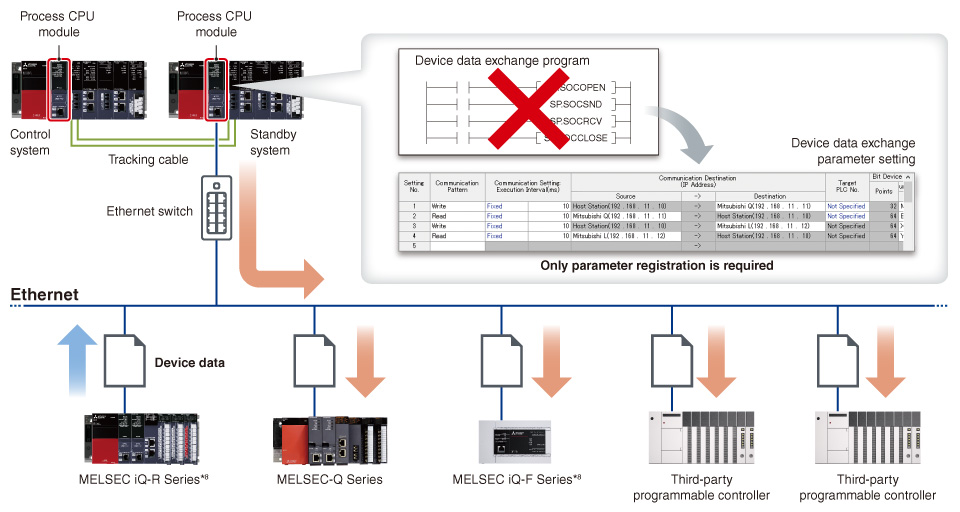
- *7.When used in the redundant system, a communication failure of the built-in CPU Ethernet is not subject to the system switching factor, but it is possible to switch the system by program.
For program examples, please refer to the MELSEC iQ-R CPU Module User's Manual (Application) (SH-081264ENG). - *8.Supported by the embedded Ethernet port only.
List of connectable devices supported by simple CPU communication function
Ethernet connection
| Communication source | Communication destination |
|---|---|
| Process CPU module (built-in Ethernet port part) |
MELSEC iQ-R (built-in Ethernet) |
| MELSEC iQ-F (built-in Ethernet) | |
| MELSEC-Q (built-in Ethernet) | |
| MELSEC-L (built-in Ethernet) | |
| SLMP-compatible device (QnA compatible 3E frame) | |
| MELSEC-A/AnS (via Ethernet interface module)*9 | |
| MELSEC-F (via Ethernet interface module)*9 | |
| RJ71EN71 | MELSEC iQ-R (built-in Ethernet, via Ethernet interface module) |
| MELSEC iQ-F (built-in Ethernet) | |
| MELSEC-Q (built-in Ethernet, via Ethernet interface module) | |
| MELSEC-L (built-in Ethernet, via Ethernet interface module) | |
| SLMP-compatible device (QnA compatible 3E frame) | |
| MELSEC-A/AnS (via Ethernet interface module)*10 | |
| MELSEC-F (via Ethernet interface module)*10 | |
| OMRON (CS/CJ Series) (FINS) | |
| KEYENCE (KV Series) (SLMP (MC protocol QnA-compatible 3E frame)) | |
| Panasonic (FP2SH/FP7 Series) (MEWTOCOL) | |
| YASKAWA MP3000 Series/MP2000 Series (extended MEMOBUS) | |
| Yokogawa FA-M3 Series (personal computer link) | |
| MODBUS®/TCP-compatible device (MODBUS®/TCP) | |
| Fuji Electric MICREX-SX Series (loader command)*11 | |
| JTEKT TOYOPUC Series (computer link)*11 | |
| SIEMENS S7 Series (S7 communication)*11 |
- *9.Supported version is “34” or later.
- *10.Supported version is “39” or later.
- *11.Supported version is “42” or later.
Serial connection
| Communication source | Communication destination |
|---|---|
| RJ71C24 | MELSEC-A/AnS Series (CPU embedded COM) |
| MODBUS® (RTU) compatible devices (MODBUS®)*12 | |
| MODBUS® (ASCII) compatible devices (MODBUS®)*12 |
- *12.Supported version is “15” or later.
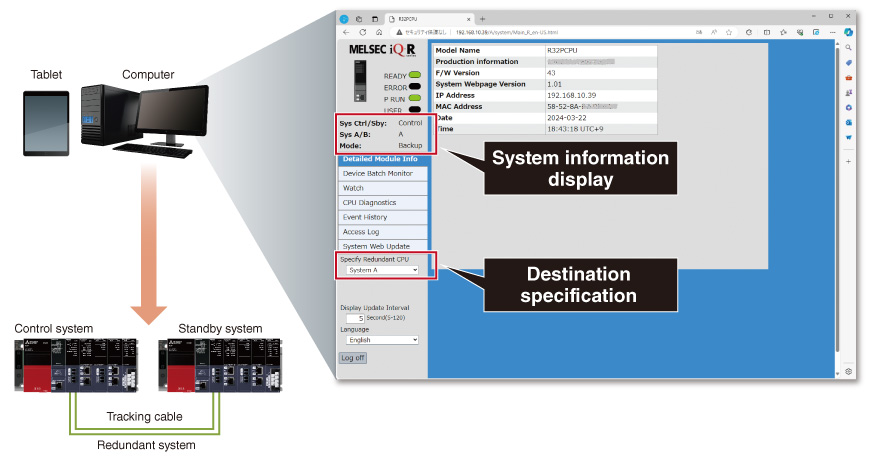
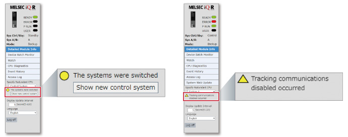
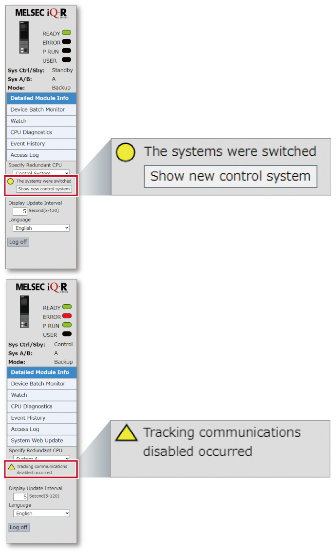
Easily diagnose and monitor redundant systems from a web browser
- CPU diagnostics and device monitoring*13 can be done via a web browser on a computer or tablet utilizing the CPU internal web server function without the need for screen creation by the customer
- Primary diagnosis when an error occurs can be easily performed without the engineering software GX Works3
- On the diagnosis screen, the system to be connected can be switched from the menu
- Information, control/standby status, and operation mode on the system (system A or B) of the currently connected process CPU (redundant mode) can be checked
- By using the “User Web Page Design Tool”, customized web page can be easily created by freely arranging provided graphic parts*14
- *13.A system web page file is required to use the web server function of the MELSEC iQ-R series CPU module. For details on how to obtain the file, please consult your local Mitsubishi representative.
- *14.For details on how to obtain the “User Web Page Design Tool”, please consult with your local Mitsubishi representative.
- The system status can be checked at a glance by displaying a message when tracking communications are disabled or systems are switched
Process CPU module/SIL2 process CPU module specifications
LD : Ladder diagramST : Structured textFBD : Function block diagramSFC : Sequential function chart
| Item | R08PCPU | R16PCPU | R32PCPU | R120PCPU |
|---|---|---|---|---|
| Operation control method | Stored program cyclic operation | |||
| I/O control mode | Refresh mode (Direct access I/O is available by specifying direct access I/O (DX, DY) | |||
| Programming language | LDSTFBDSFC | |||
| Extended programming language | Function block (FB), label programming (system/local/global) | |||
| Program execution type | Initial*15, scan*15, fixed scan, event execution*15, standby*15 | |||
| Number of I/O points (X/Y) | 4096 | 4096 | 4096 | 4096 |
| Constant scan (ms) (function for keeping regular scan time) |
0.2…2000 (setting available in 0.1 ms increments) |
|||
| Memory capacity | ||||
| Program capacity (step) | 80K | 160K | 320K | 1200K |
| Program memory (byte) | 320K | 640K | 1280K | 4800K |
| Device/label memory (ECC type)*16 (byte) | 1188K | 1720K | 2316K | 3380K |
| Data memory (byte) | 5M | 10M | 20M | 40M |
| Instruction processing time | ||||
| LD instruction (ns) | 0.98 | 0.98 | 0.98 | 0.98 |
| MOV instruction (ns) | 1.96 | 1.96 | 1.96 | 1.96 |
| E + instruction (floating-point addition) (ns) | 9.8 | 9.8 | 9.8 | 9.8 |
| Structured text IF instruction*17 (ns) | 1.96 | 1.96 | 1.96 | 1.96 |
| Structured text FOR instruction*17 (ns) | 1.96 | 1.96 | 1.96 | 1.96 |
| PC MIX value*18 (instructions/µs) | 419 | 419 | 419 | 419 |
| Interface connection port | ||||
| High-speed USB2.0 (miniB) | ● | ● | ● | ● |
| Ethernet (100BASE-TX/10BASE-T) | ● | ● | ● | ● |
| Memory interface | ||||
| SD memory card | ● | ● | ● | ● |
| Extended SRAM cassette | ● | ● | ● | ● |
| Safety standard | ||||
| IEC 61508 SIL 2 | - | - | - | - |
| Function*19 | ||||
| Multiple interrupt | ● | ● | ● | ● |
| Standard PID control | ● | ● | ● | ● |
| Process control | ● | ● | ● | ● |
| Data logging | ● | ● | ● | ● |
| Security function | ● | ● | ● | ● |
| Inter-module synchronization*20 | ● | ● | ● | ● |
| SLMP communication | ● | ● | ● | ● |
| Online module change | ● | ● | ● | ● |
| Simple CPU communication*21 | ● | ● | ● | ● |
| Web server | ● | ● | ● | ● |
| Item | R08PSFCPU-SET*22 | R16PSFCPU-SET*22 | R32PSFCPU-SET*22 | R120PSFCPU-SET*22 |
|---|---|---|---|---|
| Operation control method | Stored program cyclic operation | |||
| I/O control mode | Refresh mode (Direct access I/O is available by specifying direct access I/O (DX, DY)) | |||
| Programming language | LDST *15FBD *15 | |||
| Extended programming language | Function block (FB), label programming (system/local/global) | |||
| Program execution type | Initial*15, scan*15, fixed scan, event execution*15, standby*15 | |||
| Number of I/O points (X/Y) | 4096 | 4096 | 4096 | 4096 |
| Constant scan (ms) (function for keeping regular scan time) |
0.2…2000 (setting available in 0.1 ms increments) |
|||
| Memory capacity | ||||
| Program capacity (step) | 80K*23 | 160K*23 | 320K*23 | 1200K*23 |
| Program memory (byte) | 320K | 640K | 1280K | 4800K |
| Device/label memory (ECC type)*16 (byte) | 1178K | 1710K | 2306K | 3370K |
| Data memory (byte) | 5M | 10M | 20M | 40M |
| Instruction processing time | ||||
| LD instruction (ns) | 0.98 | 0.98 | 0.98 | 0.98 |
| MOV instruction (ns) | 1.96 | 1.96 | 1.96 | 1.96 |
| E + instruction (floating-point addition) (ns) | 9.8 | 9.8 | 9.8 | 9.8 |
| Structured text IF instruction*17 (ns) | 1.96 | 1.96 | 1.96 | 1.96 |
| Structured text FOR instruction*17 (ns) | 1.96 | 1.96 | 1.96 | 1.96 |
| PC MIX value*18 (instructions/µs) | 419 | 419 | 419 | 419 |
| Interface connection port | ||||
| High-speed USB2.0 (miniB) | ● | ● | ● | ● |
| Ethernet (100BASE-TX/10BASE-T) | ● | ● | ● | ● |
| Memory interface | ||||
| SD memory card | ● | ● | ● | ● |
| Extended SRAM cassette | ● | ● | ● | ● |
| Safety standard | ||||
| IEC 61508 SIL 2 | ● | ● | ● | ● |
| Function*19 | ||||
| Multiple interrupt | ● | ● | ● | ● |
| Standard PID control | ● | ● | ● | ● |
| Process control | ● | ● | ● | ● |
| Data logging | - | - | - | - |
| Security function | ● | ● | ● | ● |
| Inter-module synchronization*20 | - | - | - | - |
| SLMP communication | ● | ● | ● | ● |
| Online module change | ● | ● | ● | ● |
| Simple CPU communication*21 | - | - | - | - |
| Web server | - | - | - | - |
- *15.Cannot be used for safety control programs.
- *16.An extended SRAM cassette expands the device/label memory area.
- *17.The IF or FOR statement of the structured text consists of several instructions, which may increase the processing time period.
- *18.Average number of instructions such as for basic instructions and data processing executed in 1 µs. The larger the value, the faster the processing speed.
- *19.Memory dump and real-time monitor are not supported.
- *20.Inter-module synchronization is not supported when used in redundant mode.
- *21.For the list of connectable devices supported by simple CPU communication function, please refer to the “the list of connectable devices supported by simple CPU communication function”
- *22.Product package includes a SIL2 process CPU module (R□PSFCPU) and SIL2 function module (R6PSFM).
- *23.Program capacity of 40K steps is allocated for safety program.
Redundant function module specifications
| Item | R6RFM |
|---|---|
| Connection cable | Multi-mode optical fiber cable*24 |
| Laser class | Class 1 laser product (JIS C 6802:2014, IEC 60825-1:2014) |
| Maximum cable length | 550 (when the core outer diameter is 50 µm) |
| Tracking cable data capacity (word) | 1M |
- *24.For the optical fiber cable made by Mitsubishi Electric System and Service, please refer to here.