Low-voltage Circuit BreakersCircuit Breakers with Spring Clamp Terminals


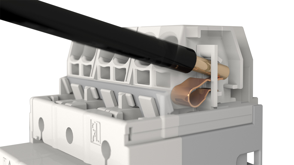
Spring Clamp Terminals
Spring clamp terminals stay connected using spring pressure to press a wire directly against the conductive section. Single wire and ferrule terminals can be connected simply by plugging them in. Even stranded wires can be connected simply by opening the spring with a tool, inserting the wire, and removing the tool.
* In our spring clamp terminals, Push-in CAGE CLAMPs of WAGO Kontakttechnik GmbH & Co. KG, Germany are used.
Three Features
Check out these amazing features!
Three major features of Mitsubishi Electric spring clamp terminals

Stable quality!
Eliminates the risk of terminal screws loosening caused by vibrations, shocks, and long-term use!

Easy wiring for anyone!
Push-in wiring does not require screw-tightening skills!

Improved maintainability!
No retightening is required during delivery or inspection of panels and mechanical equipment!
In addition,
![]()
no need to arrange and install the terminal covers!

The covered charging section ensures IP20 finger protection in all directions.
Reduced Work Time
When wired with ferrule terminals, compared to screw terminal models (with round crimp terminals)

When wired with single wire or stranded wires, compared to screw terminal models (with round crimp terminals)

* Comparison with unskilled workers (2 years of work experience) (based on a survey by the Japan Switchboard & Control System Industries Association)
Connection Reliability
Results of tests specified by JIS and IEC standards have confirmed high connection reliability!
Twist test
(JIS C 8201-7-1) (IEC 60947-7-1)


A wire is connected to a fixed terminal and twisted to check for wire disconnection.
Tension test
(JIS C 8201-7-1) (IEC 60947-7-1)


Following the twist test, a tensile force is applied and then the wire is checked for disconnection after a certain period of time.
Vibration test
(JIS C 60068-2-6) (IEC 60068-2-6)


A wire is connected to the terminal and the specified vibrations are applied in the X, Y, and Z directions to check for insulation damage or other mechanical failures. The voltage is measured before and after the test to check if the drop is within the specified range.