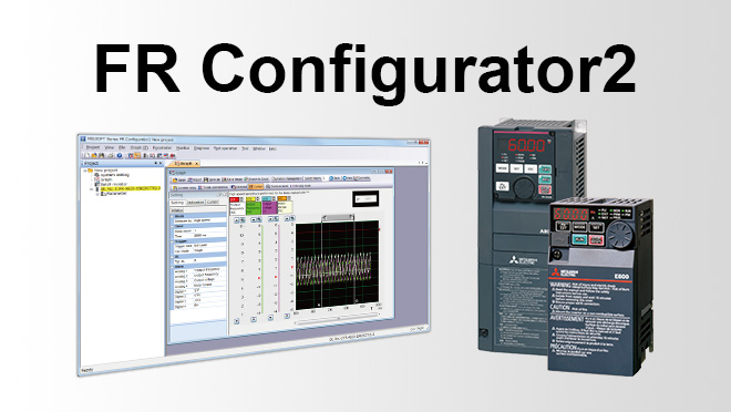
Inverters-FREQROL Software FR Configurator2 Function


From inverter startup to maintenance, this versatile software allows the user to specify settings easily at the computer.
Efficient startup settings
System settings
This sets the method used to connect the inverters and the computer. Automatic recognition of connected inverters can also be set. The station number, model, capacity, and plug-in options of the connected inverters can also be set manually.

Test operation
Operating commands, frequency settings, and the operating mode can be set for the selected inverter.

Conversion function
Parameters can be set with the parameter auto conversion function when renewing from the FR-A700 series or FR-A500 series
(to be supported soon).

Perform pre-operation adjustments and checks during operation with ease
Parameter list
Parameters for selected station numbers can be displayed and changed.

I/O signals can be assigned using settings by function.
USB memory parameter copy file edit
Parameter settings (USB memory device parameter copy file) read from the inverter to a USB memory device can be edited.
Batch monitor function
Multiple inverter monitor items can be monitored simultaneously.
With a terminal monitor, the ON/OFF status can be monitored.

Offline auto tuning
Tuning is performed in wizard format after specifying necessary parameter settings.
Easy-to-follow platform facilitates easy maintenance
Diagnosis (fault history)
Inverter fault history can be read and displayed together with the alarm occurrence time.
Activating faults can be displayed, and inverters can also be reset.

Help
Displays the content of inverter and software instruction manuals.

Graph function
Inverter data can be sampled and displayed in a graphical format. Trace data can also be read and displayed in a graph.

Life diagnosis
Life information read from the inverter is displayed. Check marks appear in the life alarm fields of inverter parts that have exceeded their replacement schedule. Diagnosis results can also be output to a file.

| Symbol | Name | Function and Description |
|---|---|---|
| A | St. No. selection (Station numberselection) | Select a station for the life check. |
| B | Last update time | Displays the last update time (system clock time of the personal computer). |
| C | Update | Updates the life information data. |
| D | Main circuit capacitor life measuring | Starts life measuring of the main circuit capacitor. |
| E | Parts life information | Displays parts life information read from the inverter. mark is shown in the alarm field for the parts recommended to be replaced. mark is shown in the alarm field for the parts recommended to be replaced. |
Ethernet parameter setting
Inverters in the same subnet mask are automatically detected, supporting easy network setting.

Troubleshooting supported by AI technology (FR-E800(-E/SCE) only)
AI fault diagnosis
The inverter is connected to the engineering software FR Configurator2 (USB/Ethernet connection).
Maisart*1 (Mitsubishi Electric's AI technology) is integrated in the software to analyze data and help identify the cause of a fault*2 (this function is enabled during speed control).
This function enables the fastest troubleshooting procedure without requiring any special skills, which contributes to downtime reduction.

- *1Maisart is Mitsubishi Electric's brand of AI technology. The name stands for "Mitsubishi Electric's AI creates the State-of-the-ART in technology". This means that it is using our proprietary AI technology to make everything smarter.
- *2Diagnosable faults: Overcurrent trip, Overvoltage trip, Inverter overload trip (electronic thermal relay function), Motor overload trip (electronic thermal relay function).
(other faults will be supported in the future.)
