Controllers MELSEC-Q Series
Product features -Network-

AnyWireASLINK
Linking the sensor with the programmable controller
AnyWireASLINK master module
DB
The AnyWireASLINK master module links the sensor inputs and outputs to the programmable controller. The module enables flexible layout of sensors with 512 I/O points. The sensor power can be supplied to the AnyWireASLINK transmission line (2-wire) for communication, allowing sensors to be added easily. With the MELSEC-Q/L/F Series, faulty sensors can be detected and the remote unit settings can be managed at once by GX Works2 engineering environment, further reducing the engineering time.

System configuration example
■ Basic configuration
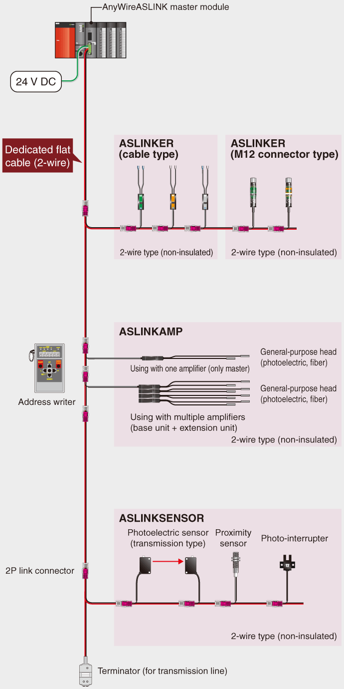
Either the 2-wire type or 4-wire remote units can be selected according to the load current for AnyWireASLINK.
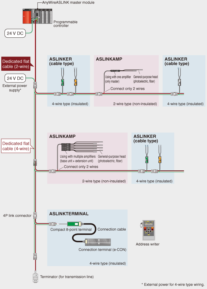
In addition to the 2-wire type, a 4-wire type can also be used by supplying the local power.
■ 2-wire type
If the load current is low, 2-wire type (non-insulated) remote units can be used without an external power supply.
■ 4-wire type
The 4-wire type (insulated) remote units require an external 24 V DC power supply to satisfy large load current applications, for example.
Configuration with 2-wire type (with no local power feed)

Configuration with 2-wire/4-wire type (with local power feed)

Preventing intermittent operation stops
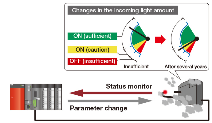
AnyWireASLINK can be used to monitor and save the sensor information within the programmable controller. Parameter settings of the AnyWireASLINK can also be changed via the programmable controller. Perform “preventive maintenance” with this function to prevent intermittent stops before they happen.
Prevent intermittent stops with preventive maintenance
- Start maintenance early by checking the incoming light amount.
- Change the ON/OFF sensitivity to keep operating up to the maintenance period.

Reducing the setup time, and providing the traceability
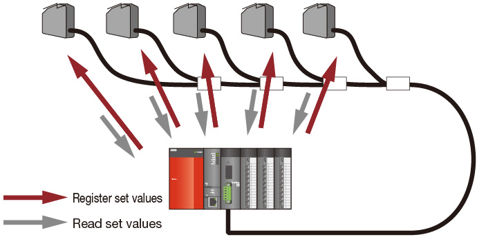
AnyWireASLINK enables the set value to be registered at once to multiple sensors via a GOT (HMI) or personal computer. Also, the initial set values can be re-confirmed easily without having to read each sensor individually.
- Register set values to multiple sensors, and automatically read the initial set values.

| Model | QJ51AW12AL |
|---|---|
| Number of connected I/O points | Max. 512 points (256 input points/256 output points) |
| Number of connected modules | Max. 128 modules (varies according to each remote unit's current consumption) |
| Maximum transmission distance (overall length)*1 |
200 m*2 |
| Transmission method | DC power superimposed total frame cyclic method |
| Connection style | Bus type (multi-drop method, T-branch method, tree branch method) |
| Transmission protocol | Dedicated protocol (AnyWireASLINK) |
| Error control | Checksum, double verification method |
| Transmission clock | 27.0 kHz |
| RAS function | Transmission cable break position detection function, transmission cable short-circuit detection function, transmission power drop detection function |
| Transmission cable (DP, DN) |
|
| Power cable (24 V, 0 V)*1 |
|
| Transmission cable supply current*1 | Using 1.25 mm2 cable: Max. 2 A Using 0.75 mm2 cable: Max. 1 A |
| External power supply | Voltage: 21.6…27.6 V DC (24 V DC -10…+15%), ripple voltage 0.5 Vp-p or less Recommended voltage: 26.4 V DC (24 V DC +10%) Module current consumption: 0.1 A Transmission cable current supply: Max. 2 A*1 |
- *1.Refer to the manual for the relation of the overall length, transmission cable (DP, DN) wire diameter and transmission cable current supply. In some remote units with cables, the wire diameter of the transmission cable (DP, DN) integrated with the module may be 0.75 mm2 or less.
- *2.With the remote units having an integrated transmission cable (DP, DN) and module, the length of the transmission cable (DP, DN) is included in the overall length.